
E7 Experimental Area
Contact Person: Ovidiu Teșileanu [ ovidiu.tesileanueli-np.ro ]
The E7 Experimental Area of ELI-NP was commissioned and set in operation in 2024 for electron acceleration experiments. Future studies will include combined laser and gamma radiation experiments, production and photoexcitation of isomers, radiation reactions, pair production in the extremely nonlinear regime, as well as vacuum birefringence. For the 8th Joint User Call, one 1 PW beam will be available as standard, while a future upgrade path will also allow combined 10 PW laser-gamma beam experiment configurations.
Laser parameters
| Parameters | Values | Comments |
|---|---|---|
| Off axis parabola | F/18, F=3,000 mm, AOI = 4.5° | Dielectric coating, 260 mm diameter |
| Beam diameter in focus | 16 µm | Minimum achieved with F = 3,000 mm |
| Beam diameter before focus | 160 mm | Full beam |
| Laser energy | 22 J | Maximum on target, about 50% encircled energy in focal spot |
| Pulse width | 22-100s fs | Ajustable through GDD variation |
| Laser maximum power | 1 PW | N/A |
| Repetition rate | 1 Hz | Single shots also available |
| Beam height | 550 mm 1,500 mm |
Above C1 and C2 optical tables Above floor level |
Main experimental geometries
- Two high-vacuum, 1,500 cubic mm enclosures (C1 and C2) have been built from aluminum and are installed in E7 along with the associated DN800 laser beam transport tubes, vacuum pumps and control system (see Figures 1 and 2). The vacuum enclosures feature DN250 and DN160 ports for mounting diagnostics and extension connections. Access for setting up the experiment is permitted through opening lateral panels. Several viewport types, with various anti-reflex coating characteristics, are available. Typical pump-down time is 60-90 minutes to reach the 1e-6 mbar range, while venting and opening the lateral panels takes 45-60 minutes. Any user-owned equipment or components that are meant to be introduced in the vacuum enclosures must be high-vacuum compatible, as well as cleaned and degassed on-site before installation.
- Two optical tables (Opt Tab 1 and Opt Tab 2) are installed adjacent to the C1 and C2 vacuum enclosures (see Figure 3). Opt Tab 1 measures 1,800 x 900 square mm and is installed at a height of 1,030 mm, while Opt Tab 2 measures 2,000 x 1,000 square mm and is installed at a height of 920 mm. An additional 2,000 x 1,200 square mm optical table can be installed at a height of 710 mm downstream of the vacuum system, after an optional extension vacuum enclosure (C3).
- The C3 extension vacuum enclosure is removable and can be connected downstream from C2 via a 300 mm DN250 bellows when extra space is needed to accommodate the experimental setup (see Figure 4). Its internal volume measures 760 cubic mm and is accessible via a large side door. Several DN250, DN100 and even smaller ports are available for installing connections or for visually inspecting the setup. When the C3 enclosure is not added to the system, an additional optical table (Optical Table 3), measuring 800 x 400 square mm, can be installed in its place at a height of 1,250 mm (see Figure 1).
- The focusing direction along the beam axis is fixed and runs parallel to the axis of the DN800 laser beam transport tubes, shifted 250 mm toward the west.
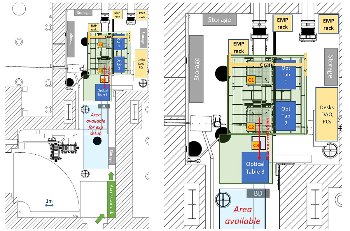
Figure 1: Block diagram of the entire E7 Experimental Area in the currently available 1 PW beam configuration (left); zoomed-in overview detailing the facilities provided around the C1, C2 and C3 vacuum enclosures (right).
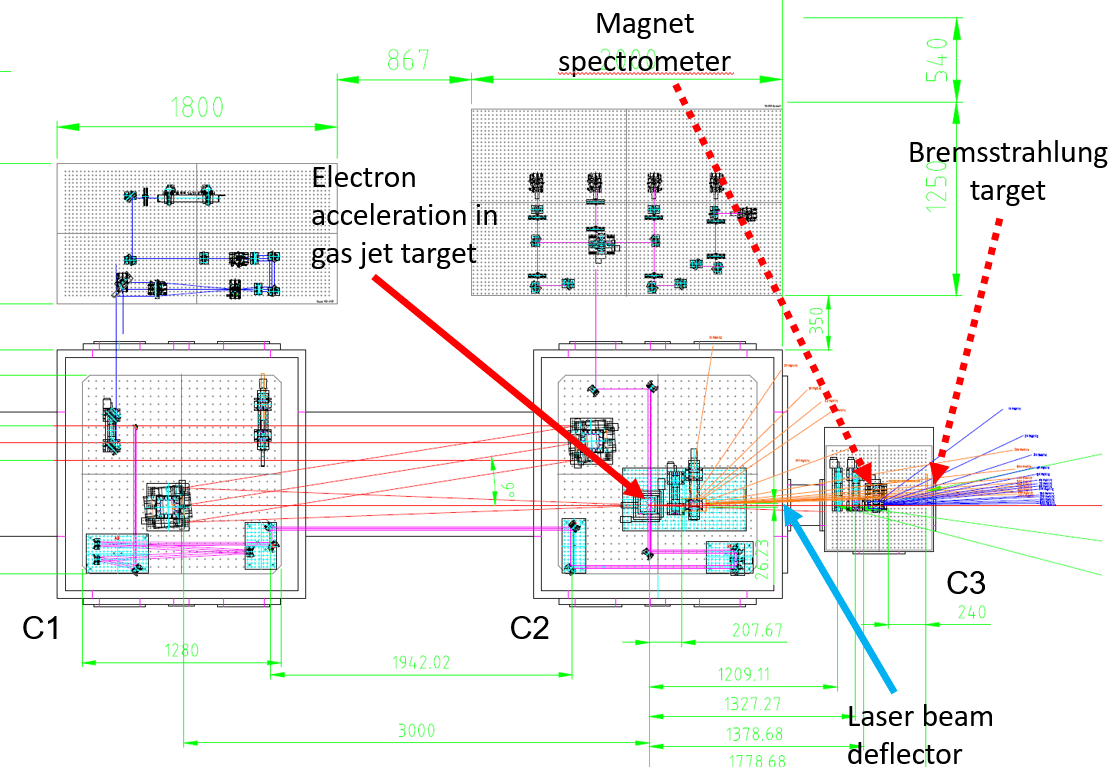
Figure 2: Example of an experimental setup used in the E7 Experimental Area, illustrating the laser beam optical path for an electron acceleration commissioning experiment.
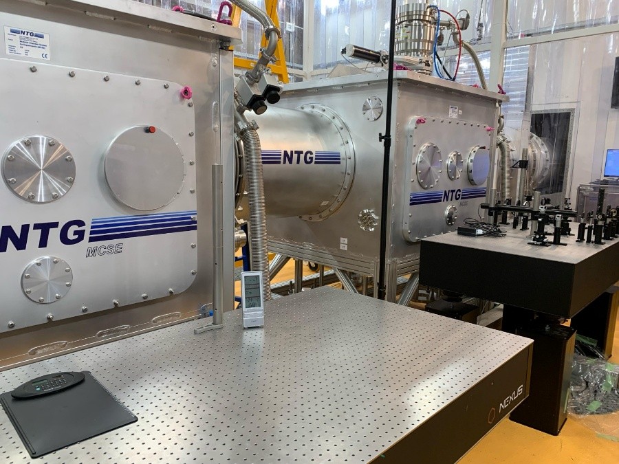
Figure 3: Photograph of the two main vacuum enclosures available in the E7 Experimental Area, C1 (right) and C2 (left).
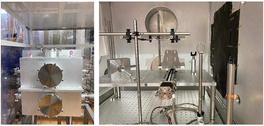
Figure 4: The C3 extension vacuum enclosure available in the E7 Experimental Area, photographed externally (left) and internally (right).
- The E7 Experimental Area was commissioned in 2024 with an experiment studying electron acceleration using gas-jet targets, followed by Bremsstrahlung high-energy photon generation (see Figure 2). The laser wake-field acceleration (LWFA) mechanism was investigated employing a 1 mm long gas-jet comprised of a mixture of He + 2% N2. The laser beam was focused down to a diameter of 16-18 μm with good stability (see Figure 5).
- Considering the application for high-energy photon generation, the parameter space for electron acceleration was scanned in order to optimize for the collimation and high charge of the accelerated electron bunches. Samples of electron traces on the DRZ scintillator screens are presented in Figure 6, showing peak electron energies attained in the range of 200-500 MeV.
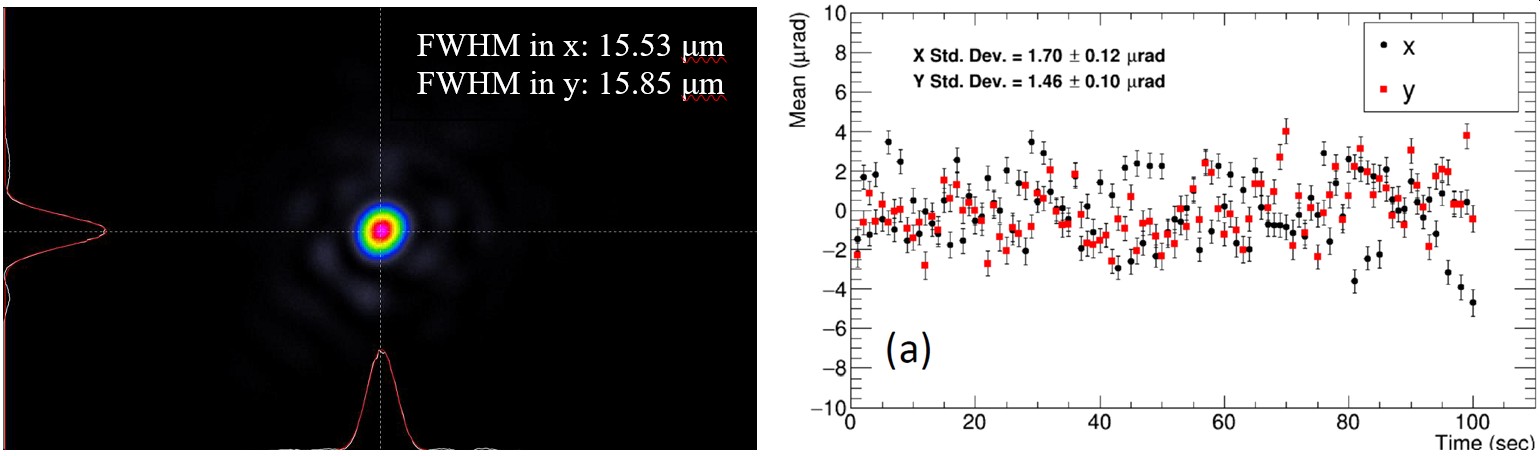
Figure 5: Focus spot sample achieved in the E7 Experimental Area (left) and pointing stability of the laser, measured for 100 consecutive pulses (right).
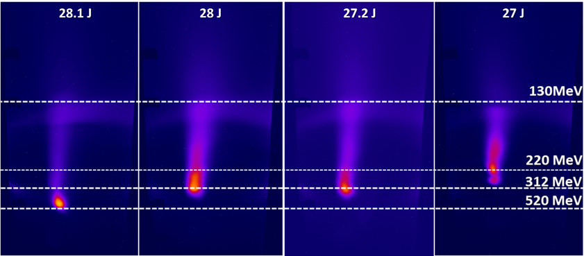
Figure 6: Electron trace samples for the gas mixture He + 2% N2, captured on the DRZ scintillator screens during the optimization for collimation and high charge. The quoted laser pulse energy is measured before the compressor.
Permanent diagnostics
| Diagnostic | Technique | Model |
|---|---|---|
| Laser diagnostics at input | Energy (μJ-J ranges), pointing, wavefront | Gentec QE95LP-S-MB-QED-D0 (10 µJ - 2.5 mJ) and QE8SP-B-BL-D0 (1 mJ - 250 J); Phasics SID4-H; Basler acA2440-20gm |
| Optical spectra | Optical spectrometers in visible and near-infrared | Ocean Optics HR4000 CG-UV and NQ512-1.7 |
| Photon detection | (Fast) photodiodes, 200-1,100 nm | Thorlabs DET025A/M, DET10A2 and DET08C/M; Alphalas UPD-35-UVIR-P |
| Electron diagnostics | Energy spectrometers | 50 mm, 160 mm and 140 mm long dipole magnets with various field strengths and gaps (3D maps available); scintillator screens (DRZ) of various sensitivities |
| Plasma diagnostics | Shadowgraphy, wavefront sensor | Basler acA2440-20gm; Phasics SID4-HR |
| High-energy photon detection | Scintillator detectors | 2 x LaBr 1.5-inch crystal detectors, with PS and 250 MHz digitizer |
Targetry
- For gas-jet targets, a SourceLab A2-6443 electromagnetic valve fitted with a Smartshot LX-03R fast solenoid valve controller is available to the users (more details can be consulted here). ELI-NP usually stocks pure He, Ar and pre-mixed He+N2 in various fractions, but other gas species may be requested for specific user experiments. When using gas jet targets, a reduced repetition rate of the main laser will be used (typically, 1 pulse every 20-30 seconds) to allow enough time for the recovery of the vacuum level.
- Due to the radioprotection regulations, users must keep the pre-designated beam direction for the acceleration of particles using medium density gas-jet targets. Presently, E7 is authorized for gaseous target experiments, with secondary Bremsstrahlung targets also possible. For the future, there is already a plan to extend the experimental area's authorization for solid targets as well.
Triggers
- The triggers from the main laser system are available from -100 ms to -2 ms, after which local delay generators can be used to provide more precise triggers within the E7 Experimental Area (Stanford Research Systems DG645, manual can be consulted here).
Cleanroom requirements
- The entirety of the vacuum and optical systems are located within an ISO7 soft-wall cleanroom. Any equipment or components brought in by users for the experiment must also observe this standard.