E5 Experimental Area
Contact Person: Mihail Cernaianu [ mihail.cernaianueli-np.ro ]
The E5 Experimental Area of ELI-NP has been successfully commissioned and set in operation by the year 2022. For the current User Call, the system is now optimized for running both short and long focal experiments with a single beam, while two-beam synchronization is not yet available.
Laser parameters
| Parameters | Values | Comments |
|---|---|---|
| Beam diameter before focus (FWHM) | 190 mm | |
| OAP | F/3.7, f = 0.707 m, 45 degree F/26, f = 5.03 m, 90 degree | F/26 is installed in C3 and focuses in C1 |
| * Beam diameter after focus (FWHM) | ~3.5 um (F/3.7) ~25 um (F/26) |
|
| Laser energy | 25 J (each beam) | |
| Repetition rate | 1 Hz as well as single-shot | |
| Pulse width | 24 fs - 1 ps | |
| Laser max power | 1 PW |
*One beam available as standard (beam A or B) at this point. Two-beam experiment configurations will be accommodated in the future. When two-beam experiments will be made available, the short and long parabolic mirrors will focus the beams in the main interaction chamber, C1. Please contact the local coordinator for a detailed drawing of the possible configurations.
Experimental chambers
- C1 (interaction chamber)
-
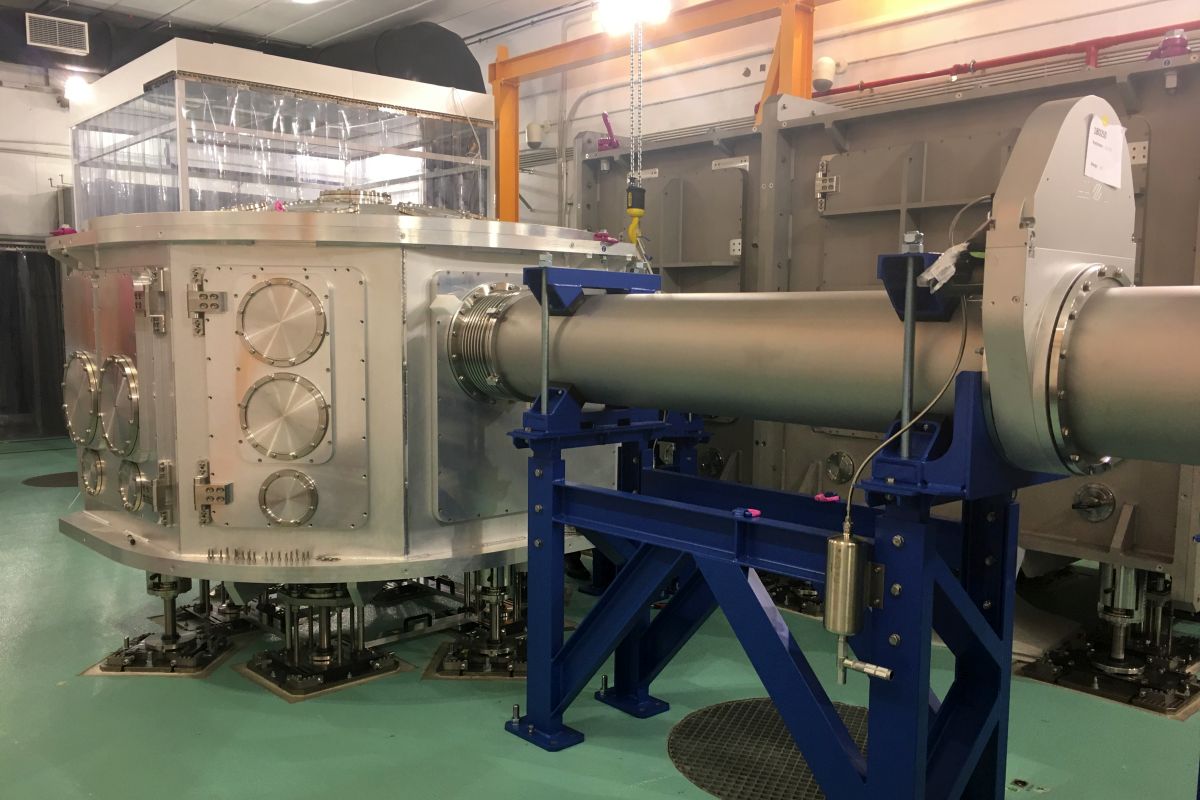
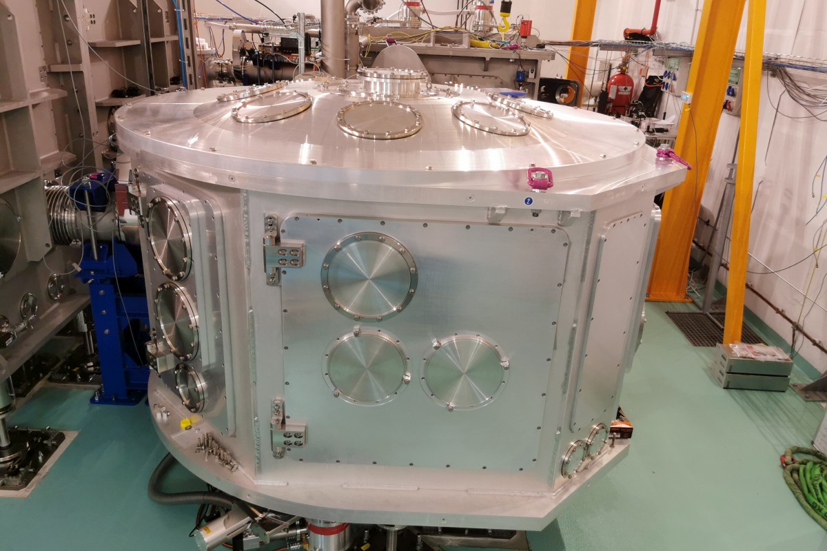
The C1 chamber is approximately 2 m in diameter and 1.4 m in height.
| Beams | Heights |
|---|---|
| Long focal beam axis | 1.51 m from the floor 0.76 m from the optical table |
| Short focal beam axis | 1.15 m (up to 1.51 m) from the floor 0.40 m (up to 0.76 m) from the optical table |
Main experimental geometries
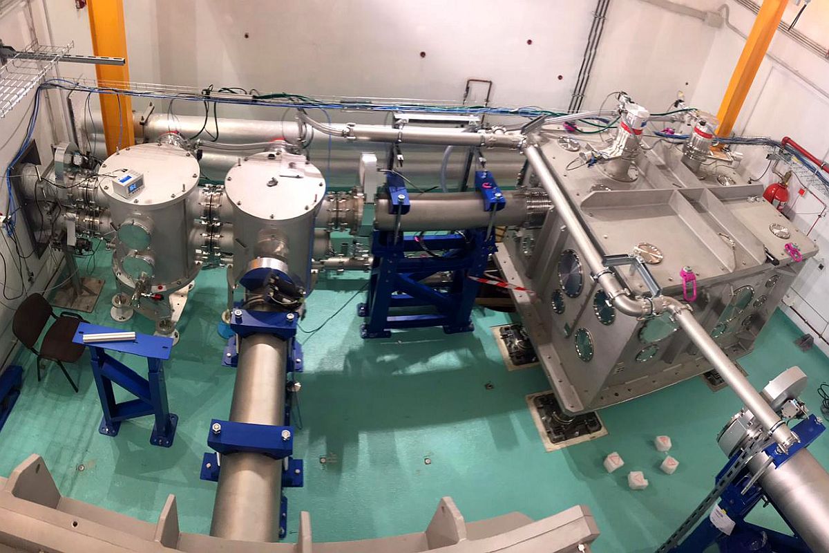
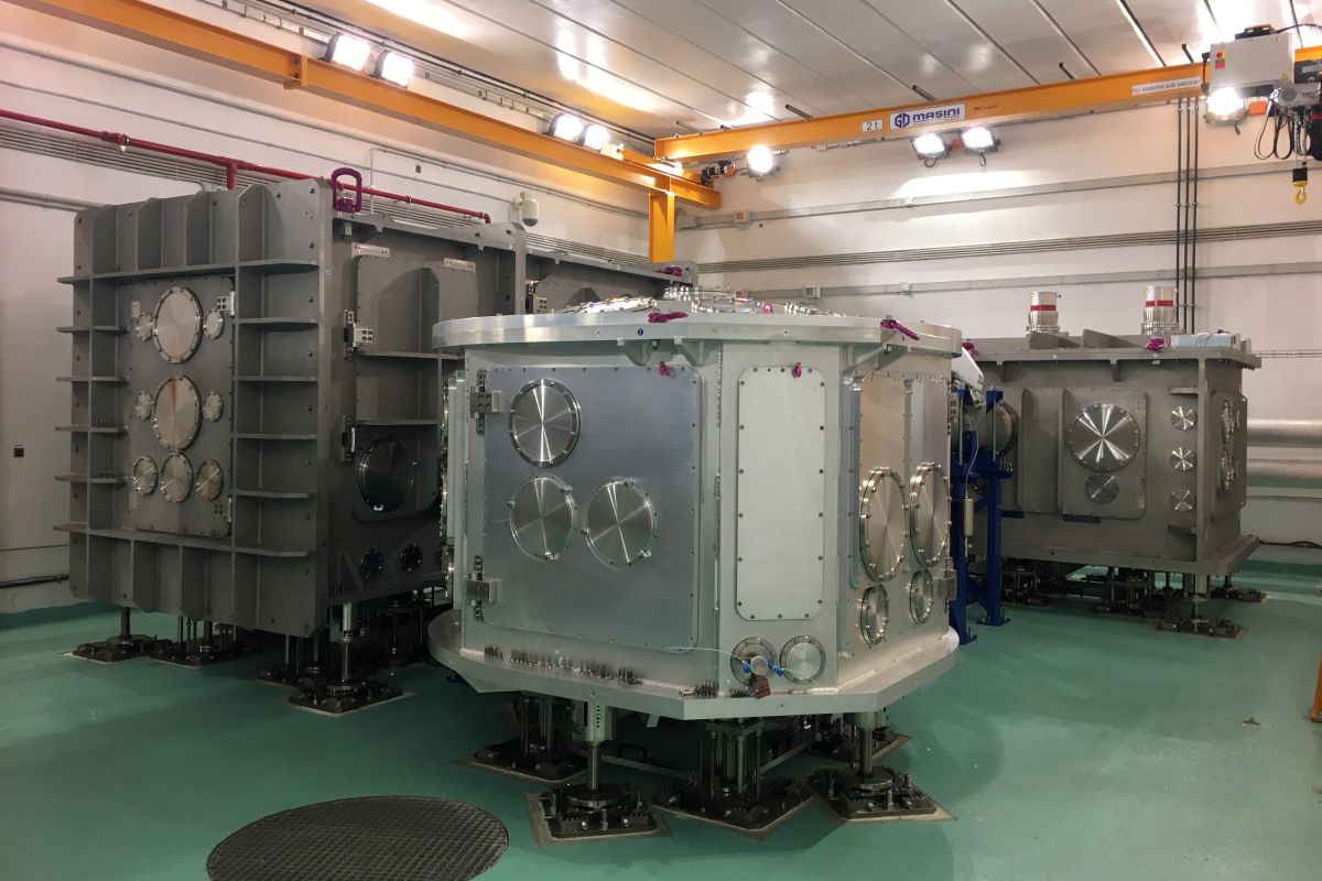
- Three large vacuum chambers have been built and installed, denominated C1, C2 and C3, along with turning boxes for the beam transport. C1 is the main interaction chamber, while the other two are used to deliver the short focal beam (C2) and the long focal beam (C3) into the interaction chamber (C1), as well as allow further setups to be installed (e.g. waveplates, laser back reflection monitoring) [D. Doria et al. 2020, K. A. Tanaka et al. 2020].
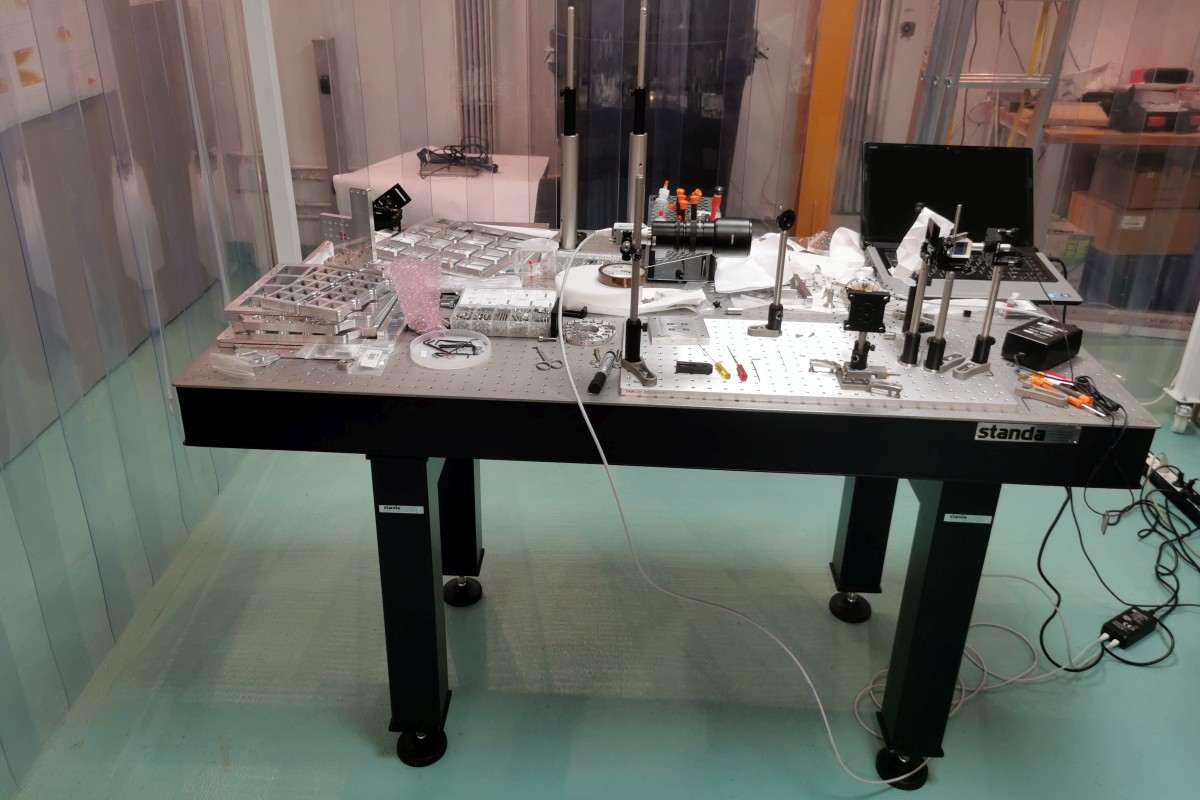
- Optical tables are available near the vacuum chambers.
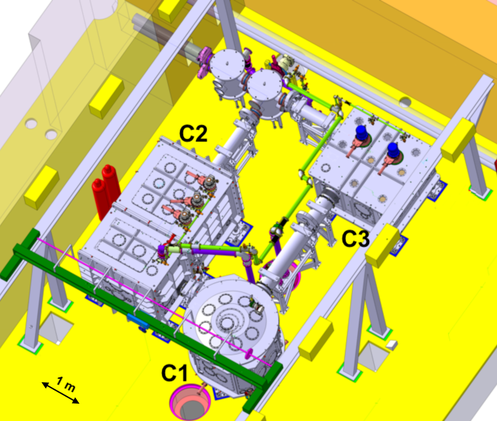
Figure 1: CAD model of the E5 Experimental Area.
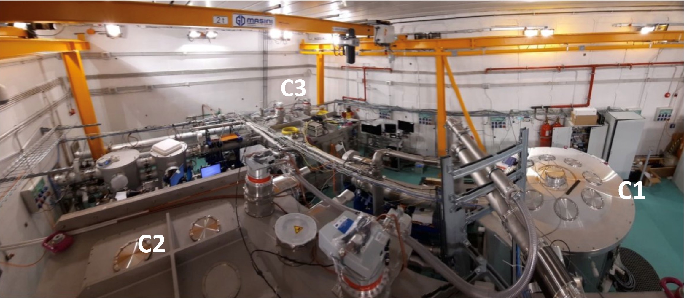
Figure 2: Top view of the E5 Experimental Area with the interaction chambers C1, C2 and C3.
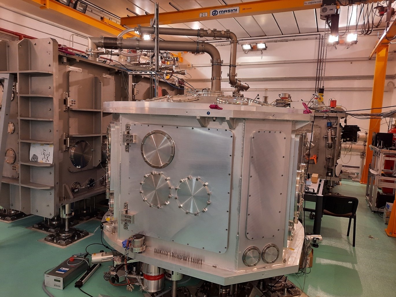
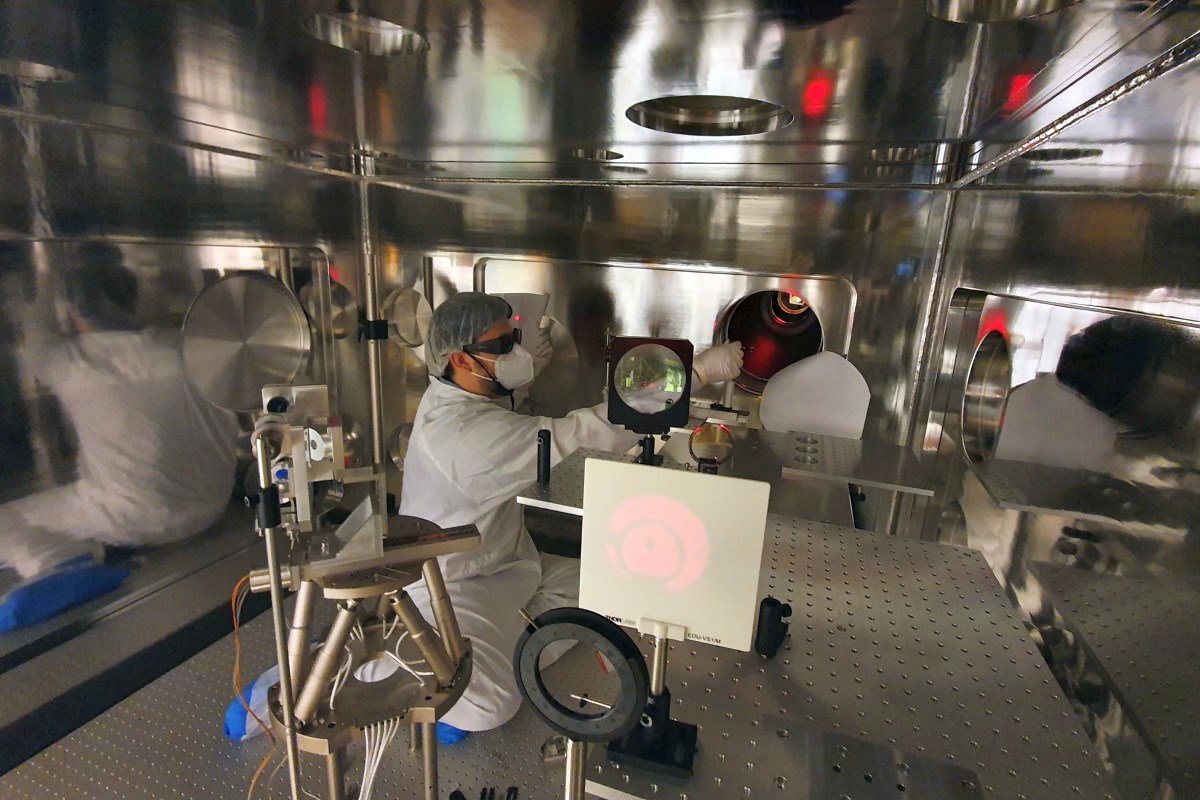
Figure 3: The C1 interaction chamber of the E5 Experimental Area.
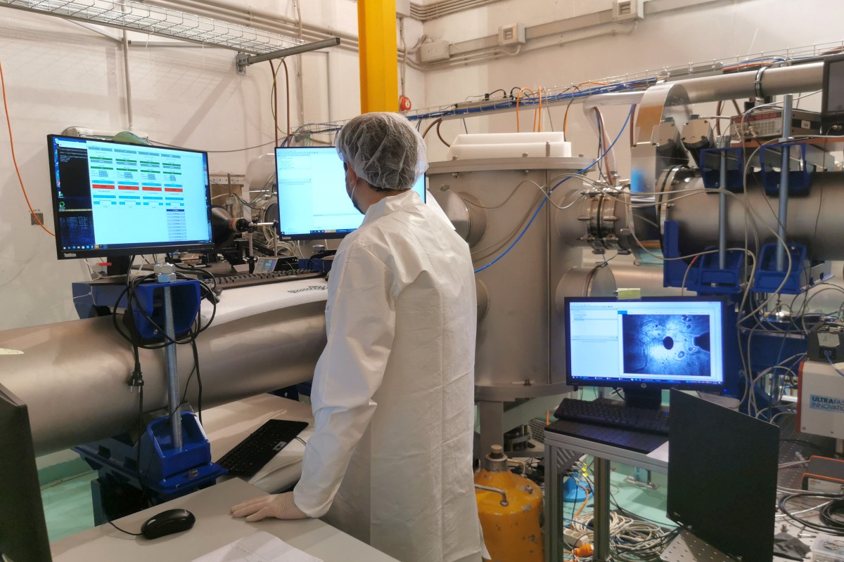
Commissioning results
In the second half of 2021, ELI-NP began commissioning its 1 PW Experimental Area - E5. The campaign was centered on the characterization of one of the two High Power Laser System (HPLS) arms. The experiment focused on the laser-driven acceleration of ions, with the aim of testing the performance of the laser system at 1 PW, as well as the readiness of the E5 Experimental Area for such experiments using both solid targets (Figure 4) and gas targets (Figure 5).
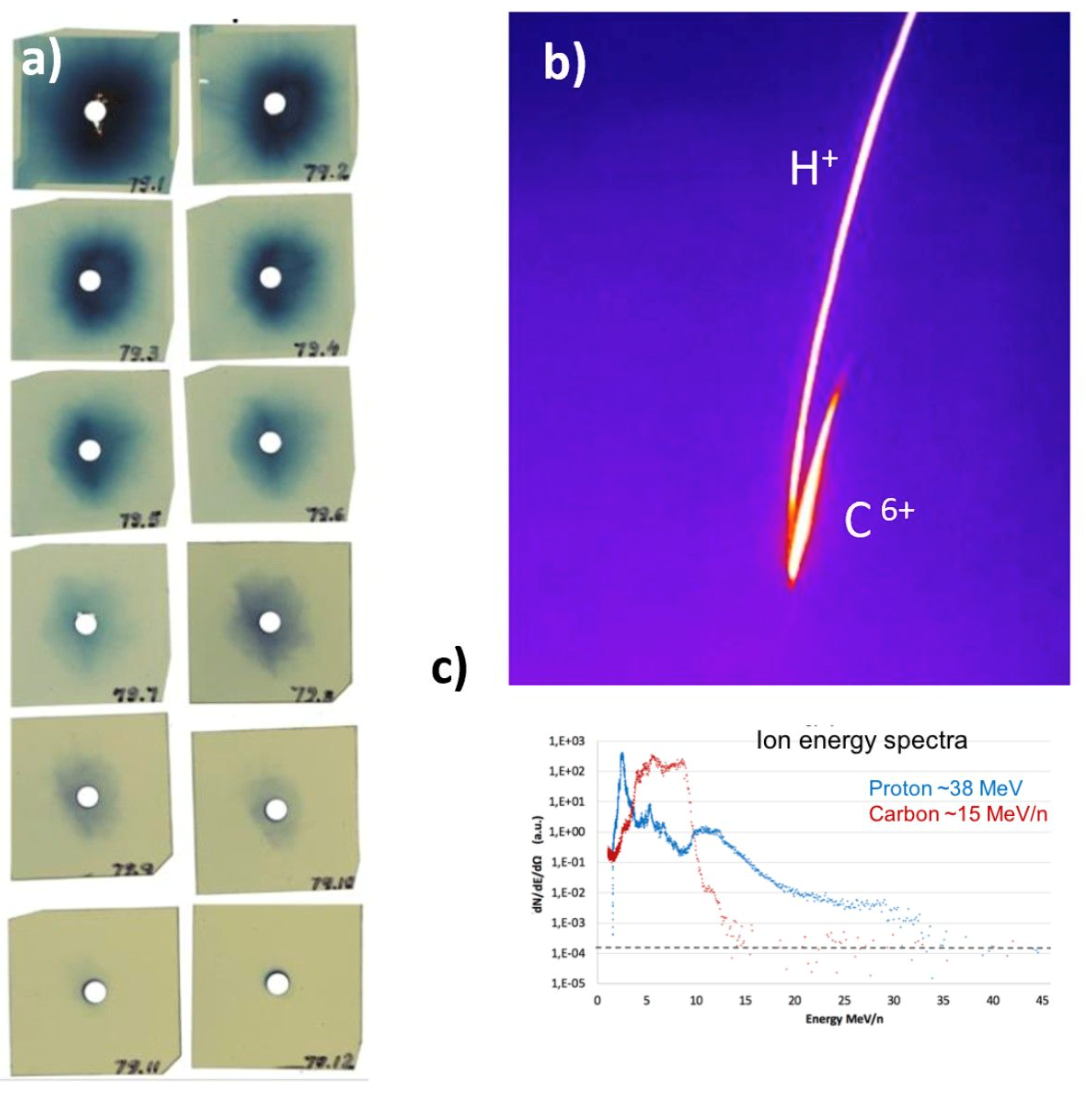
Figure 4: a) Radiochromic film stack and b) Thomson parabola signals obtained by shooting a 19 J laser beam via a plasma mirror onto a diamond-like, 380 nm thick carbon target.
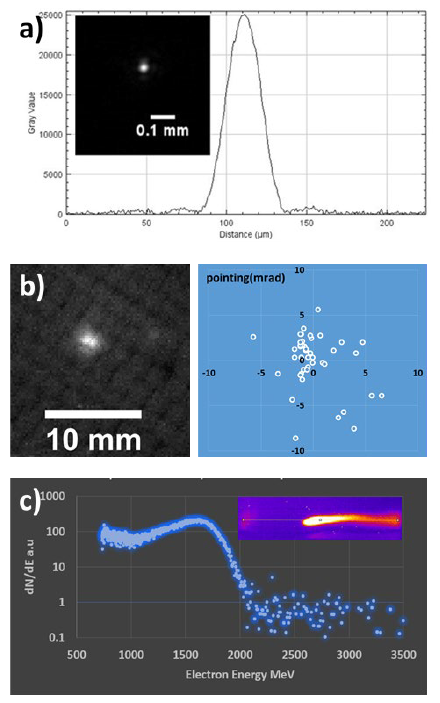
Figure 5: a) Focal spot typically obtained with the long focusing mirror; b) Electron beam divergence measured before the electron spectrometer; c) Energy obtained with a 20 mm 3D-printed gas cell.
Laser alignment and target manipulation
- Linear/circular polarization: mica waveplates;
- 5x-40x objective alignment system, 1 μm spatial resolution target motion;
- Deformable mirror;
- Single plasma mirror;
- Shack-Hartmann wavefront sensor/100 R.M.S. 32x40 pixels.
Laser diagnostics
- Contrast measurement in the HPLS bay;
- Far-field and near-field measurements;
- Energy, spectrum and pulse duration measurements (FROG);
- Back-reflection monitor at full power.
Particle detection
- Detector stack: 1” x 1” up to 60 MeV protons (radiochromic film, CR39);
- Thomson parabolas: up to 60 MeV, 8% resolution @ 60 MeV, image plate detector (optical coupling optional for online detection);
- Optical plasma probe (as a pick-up from the main laser beam): 1w or 2w, ½-1” diameter and up to 100 mJ with pulse duration as the main laser beam, for interferometry and shadowgraphy;
- e- Spectrometer for low energy electrons: up to 10s MeV;
- e- Spectrometer for high energy electrons: up to 2 GeV;
- Optical spectrometer: ANDOR Shamrock (VIS), UV-Vis-NIR spectrometer with optical fiber.
Triggers
- The triggers from the main laser system are available from -100 ms, then a local delay generator can be used for more precise triggers in the E5 Experimental Area (i.e. a Stanford Research Systems DG645 unit, manual available at https://www.thinksrs.com/downloads/pdfs/manuals/DG645m.pdf
Cleanroom requirements
- The E5 Experimental Area has not been officially certified as such but has a cleanliness equivalent to the ISO-8 standard, while an ISO-7 soft-wall cleanroom is also present and available for use. All of the components brought in by the users for performing their experiment must observe these cleanliness standards.
References