E4 Experimental Room
Contact Person: Madalin Rosu [ madalin.rosueli-np.ro ]
Laser Parameters
| Parameters | Values | Comments |
|---|---|---|
| Off Axis Parabola | F/8.5, F=520 mm, AOI = 7.5° F/25, F=1500 mm, AOI = 6.25° |
Au coating Au coating |
| Beam diameter in focus | 5-22 um | depending on focal length |
| Beam * diameter before focus | 60 mm | full beam |
| Laser Energy | 2.2 J | maximum |
| Pulse width | 22-100s fs | |
| Laser Max. Power | 100 TW | |
| Repetition rate | 10 Hz | single shot also available |
| Beam height | 225 mm 1030 mm |
above optical table in VE1 and VE2 above floor level |
* One beam available as standard (beam A) at this point. Two-beam experiment configurations will be accommodated in the future.
A secondary laser system is available locally in E4: Litron Lasers LPY 7864G-10, Nd:YAG Single Longitudinal Mode, which can be synchronized with the main laser system.
2nd and 3rd harmonic modules are available:
https://litron.co.uk/product-range/high-energy-lasers/lpy7000-range/
Also, a local He-Ne alignment laser is available in the area.
Main Experimental Geometries
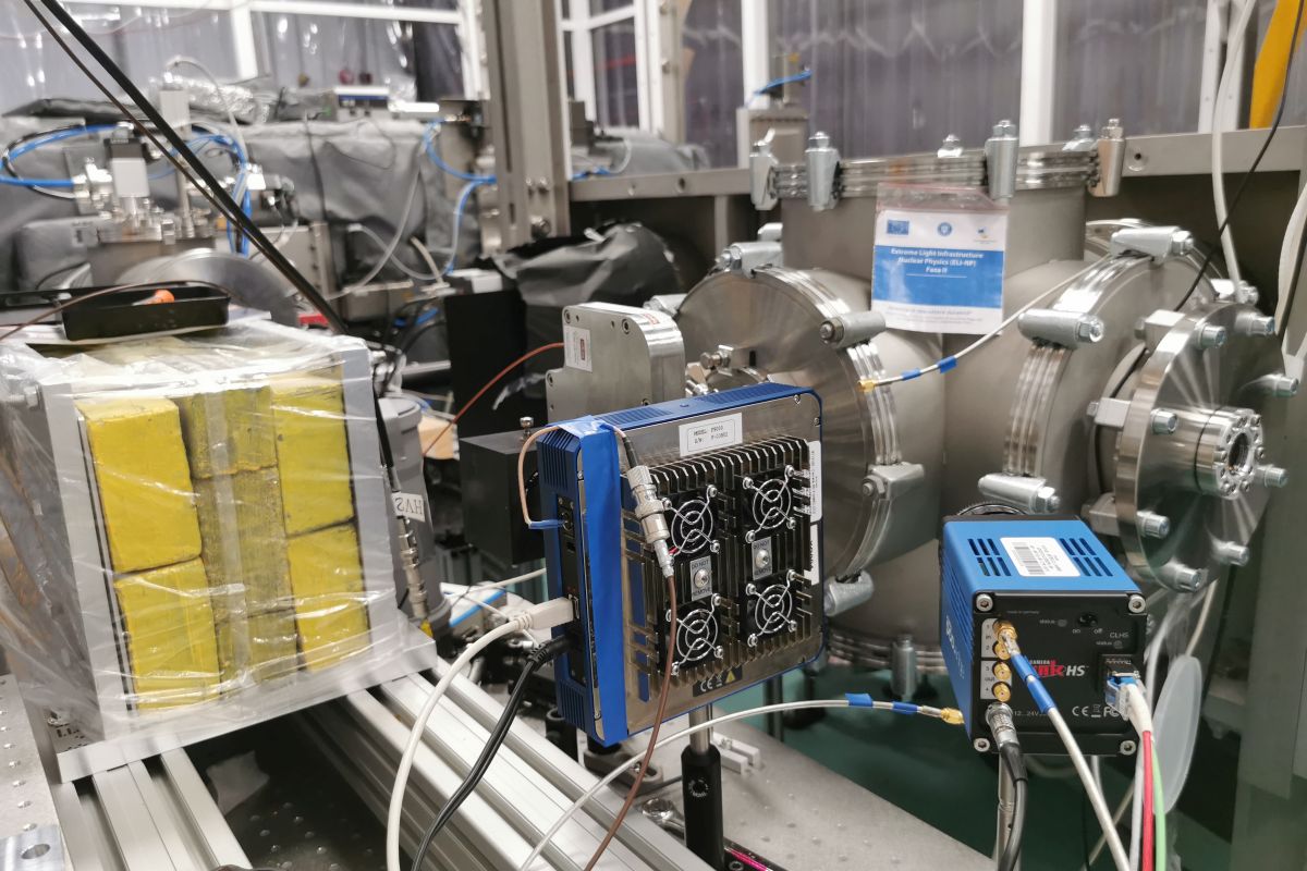
- Two large vacuum chambers have been built and installed, one for high vacuum and one with ultra-high vacuum specifications. Both use DN250 and DN160 CF flanges for viewports and other components of the setups. The ultra-high vacuum chamber (VE2) has bake-out capabilities up to 200°C and cryopump in addition to two high-capacity turbomolecular pumps. The vacuum system has a centralized command and control system.
- Three optical tables (one of 2400 x 1500 mm area and two of 900 x 1800 mm, adjustable height, set at 805mm currently) are installed in the area (see sketch in Fig.1). The beam transport pipes enter E4 at two different heights, and after entering the area they are taken to the same reference height of 1030 mm with respect to the floor. A system of turning boxes and beam transport pipes guide these beams to the large optical table and to the two large vacuum enclosures.
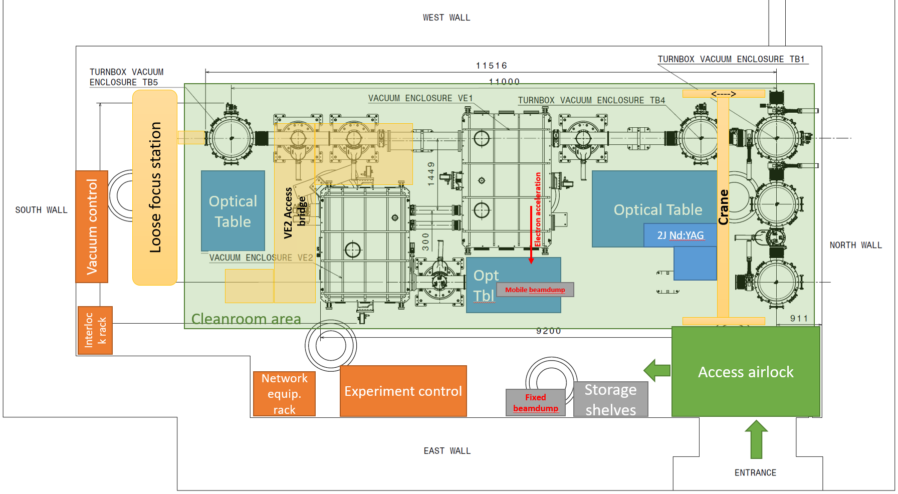
Figure 1. Block diagram of the E4 experimental area in the current single beam configuration.
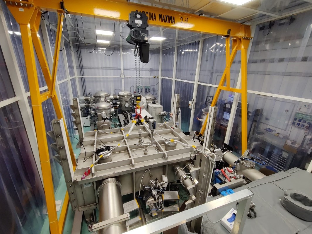
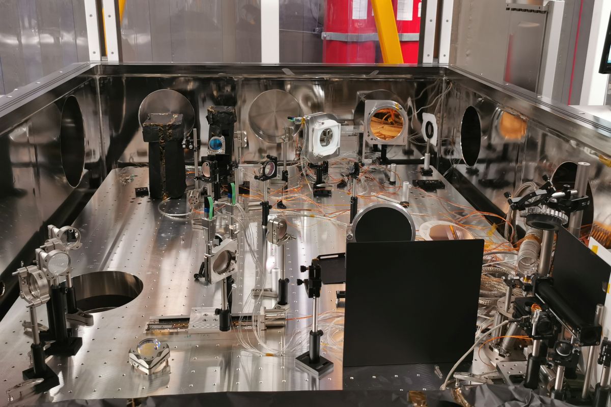
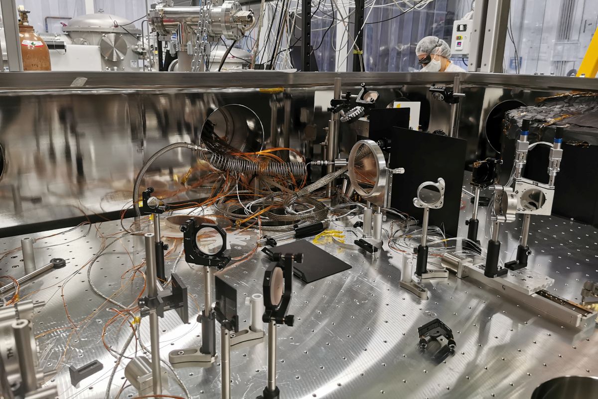
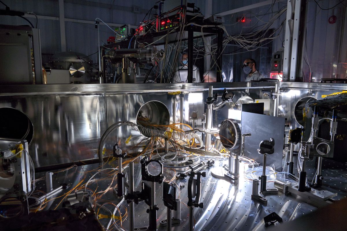
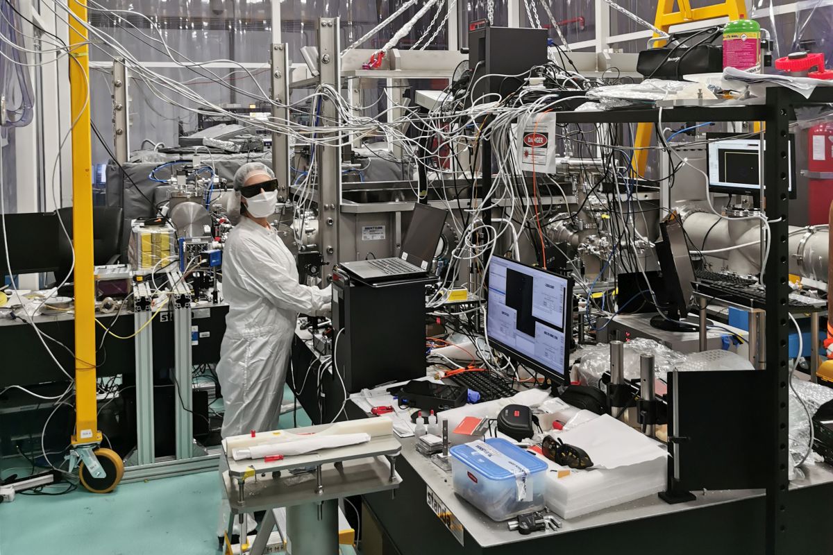
Figure 2: Overview of the E4 experimental area, as seen from the VE2 access bridge, towards North.
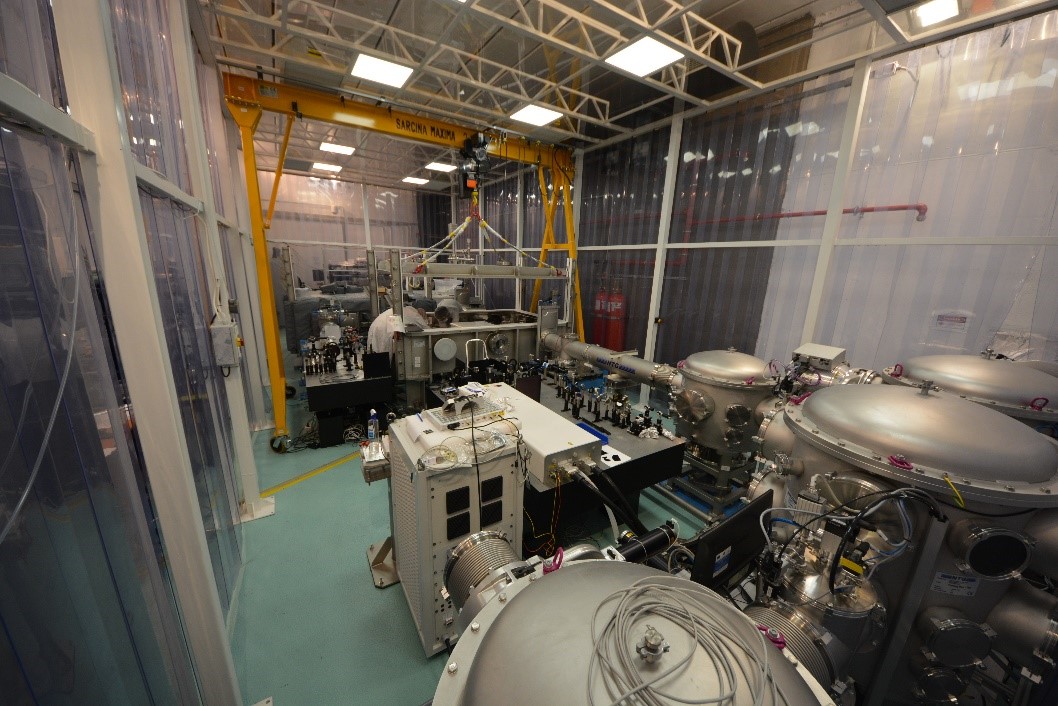
Figure 3: Overview of the E4 experimental area, as seen from the North wall.

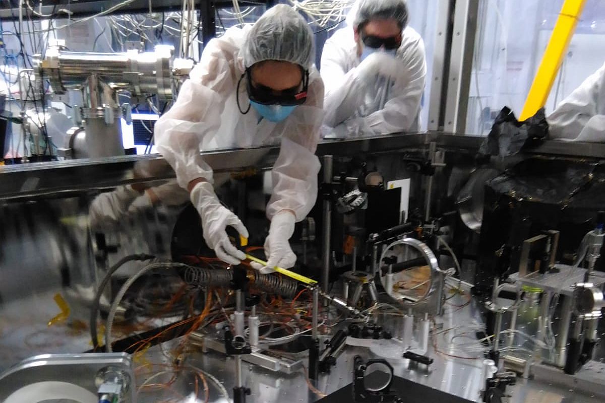
Figure 4: Image from E4 with the VE2 vacuum chamber and its access bridge, and part of VE1.
E4 was the first experimental area to enter operation at ELI-NP, in 2020. The experiment consisted in assessing the performance of the HPLS by the acceleration of electrons from a gas target
(the setup is presented in Fig. 5). The laser wake-field acceleration (LWFA) mechanism was investigated employing a 2 mm long gas-jet with either pure Helium gas
or a mixture of Helium plus 2% Nitrogen. The beam was usually focused down to a normalized vector potential a0 = 2.6±0.3 by using a parabolic mirror of focal length of 1500 mm.
For each type of gas target, the gas density and the laser focus position were scanned to find favourable conditions for the interaction. The images of the laser channel in the gas through
optical probing, and the profile of the electron beam onto an on-axis Lanex screen were used to seek for the optimum conditions. An example is reported in Figure 6.
The maximum electron energy attained with the Helium gas was of about 220 MeV with an energy spectrum having a certain degree of monochromaticity. The maximum energy reached using the
admixture was about 320 MeV with a continuum energy spectrum, as typically expected when using a dopant such as the Nitrogen. The raw images from the LANEX screen of the electron traces, for both cases, are shown in Figure 7.
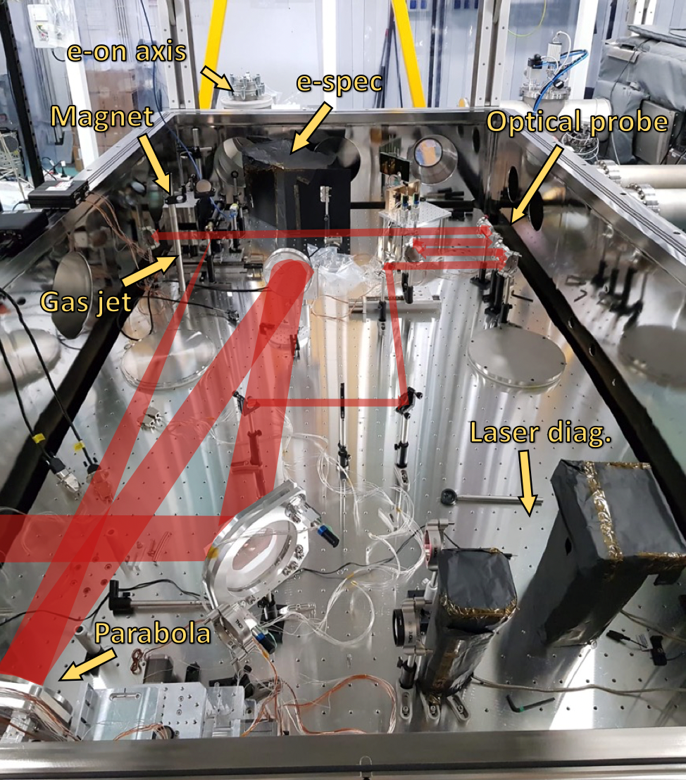
Figure 5: The LWFA experimental setup in VE1 chamber. The laser beam path is shown in red, and the most relevant diagnostics and apparatuses used are mentioned with a yellow label.
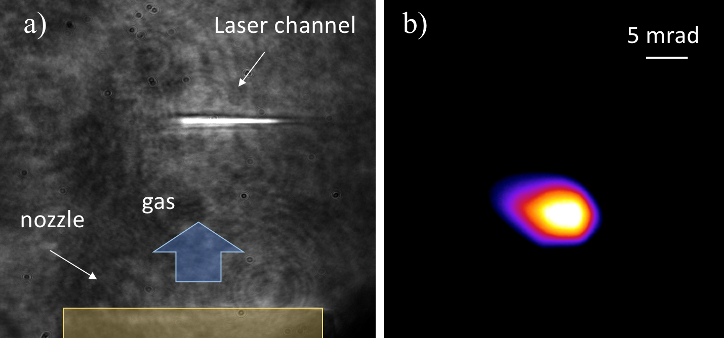
Figure 6: a) Shadowgraphy signal (side view diagnostic) of the channel created by the laser at about 10 ps from the beginning of the interaction. b) example of a good electron beam profile, as obtained from the process of optimization of the LWFA. The optimized electron beam divergence was about 5 mrad FWHM, with pointing fluctuation of about ±5 mrad.
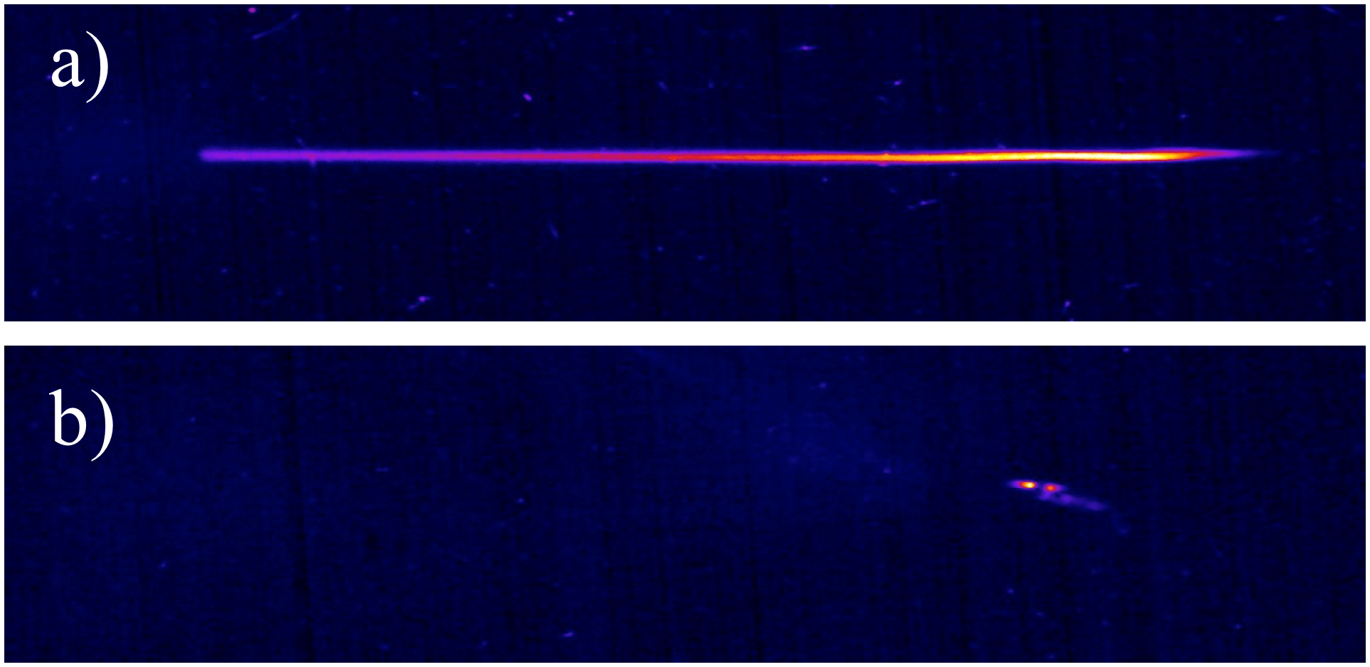
Figure 7: a) electron trace on LANEX for the case of gas admixture, and b) for the case of pure Helium gas.
Permanent Diagnostics
| Diagnostic | Details/Technique | Producer/model |
|---|---|---|
| Laser diagnostics at input | energy (uJ-J ranges), pointing, wavefront | Gentec QE95LP-S-MB-QED-D0 (10uJ-2.5mJ), QE8SP-B-BL-D0 (1mJ-250J), Phasics SID4-H, Basler acA2440-20gm |
| Photon detection | photomultipliers 300-700 nm | Hamamatsu H10721-110, H10721-20 |
| Optical spectra | Optical Spectrometers in Visible and near-infrared | Ocean Optics HR4000 CG-UV and NQ512-1.7 |
| Photon detection | (fast) photodiodes 200-1100 nm | Thorlabs DET025A/M, DET10A2, DET08C/M, Alphalas UPD-35-UVIR-P |
| Electron diagnostics | spectrometer (up to 500 MeV) | 16 cm long dipole magnet with about 0.7 T B-field, and a Lanex screen |
| Plasma diagnostics | shadowgraphy |
Targets
For gas jet target, we have a SourceLab valve with controller SL-Smartshot (fast solenoid valve driver LX-03R and electro-magnetic valve A2-6443) available to use.
Manual available online: https://www.sourcelab-plasma.com/targetry-catalog/medium-density-gas-jet/
Please inquire about about gas availability. Also, a mobile electron beam dump is available upon request.
Since this target area was designed for electron acceleration, solid targets might be possible, but expected secondary radiation
calculations and radiation safety approval would be needed.
We ask Users to use the HV chamber and shoot perpendicular (East-West direction) to the incoming beam direction.
Triggers
The triggers from main laser system are available from -100 ms to -2 ms. Then local delay generator can be used for more precise triggers
in the experimental area (Stanford Research Systems DG645, manual available at
https://www.thinksrs.com/downloads/pdfs/manuals/DG645m.pdf .
Cleanroom Requirements
The entire vacuum and optical systems are located in an ISO7 soft-wall cleanroom. All components brought in by users for the experiment must observe this standard.